What Fiber Damage Locator does
Fiber Damage Locator turns an OTDR trace and your route documentation into a GPS pin on a map — the estimated real-world location of a fiber break, ready to hand to a splice crew or a customer's design team. No cable locators, no driving every span of the route looking for damage.
It works two ways: import your fiber route from your mapping system (most accurate), or draw the route manually if you don't have documented plant data for that circuit. Either way, once an OTDR trace is attached, the fault distance from the trace is walked along the route geometry to produce a real-world position.
Signing in for the first time
Start a free 7-day trial at /signup — no credit card required, full access to the Fiber Damage Locator from day one. Once you're signed in you'll land on the tool itself, ready to bring in your first route.
Why your GIS export matters
This is the single biggest factor in how accurate your fault location comes out — more important than anything else in this guide.
The tool doesn't just draw a straight line from Point A to Point B and call it done. It walks the actual documented splice/vault points along your route, and the confidence circle you see around the fault pin is calculated directly from the gap between the two nearest documented points on either side of the fault.
A sparse export — just the start and end address of a circuit — gives the tool almost nothing to work with in between. The result is a wide uncertainty circle, because the tool is honest about not knowing exactly how the cable runs for miles between those two points.
A rich export — every splice case, vault, and slack point your GIS system has recorded along that route — lets the tool narrow the fault down to a tight, trustworthy circle, sometimes down to a single confident point.
Before you import, from your GIS/mapping system:
- Export every splice case/vault point along the route, not just the two endpoints
- Include the measured cable footage between each pair of points, if your system tracks it — this becomes the slack the tool uses to walk distance accurately
- Double-check the export actually covers the full circuit end-to-end, not just the segment nearest the reported trouble
The extra five minutes spent pulling a complete export is almost always cheaper than the time lost sending a crew to the wrong span.
The two ways to bring in a route
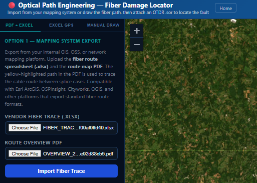
Option 1 — GPS Coordinates Export (Excel or CSV)
Export splice case GPS coordinates and measured cable footage from your mapping system — Esri ArcGIS, OSPInsight, Cityworks, QGIS, or any system that produces a compatible spreadsheet or CSV. The route is built automatically between each point, following roads where a road plausibly runs along the fiber's actual path and a direct line where it doesn't. This is the mode described above — the more complete the export, the more accurate the result.
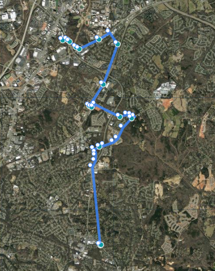
After import, drag any waypoint on the map to match the actual cable path — buried conduit, aerial spans through a field, or anywhere the automatic routing didn't get it exactly right.
Option 2 — Manual Draw
If you don't have documented route data for this circuit, enter a start (and optionally end) address and draw the path yourself. Click the line to add waypoints, drag to adjust, undo if you make a mistake. This mode uses raw geographic distance along the line you draw rather than documented cable slack, so it's inherently less precise than a real GIS export — use it when nothing better exists, not as a first choice.
Uploading an OTDR trace
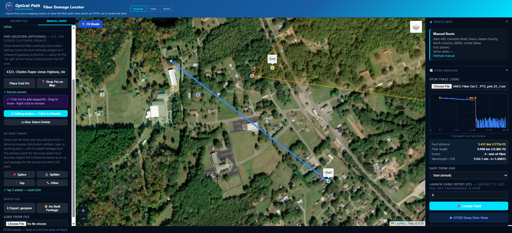
Once your route is loaded, attach the OTDR trace from the fault event. The trace is parsed for its event table, loss profile, and fiber length — the fault distance is identified as the first reflective or loss event past the launch cable, then walked along your route to a real-world position.
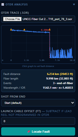
This tool reads the industry-standard Bellcore/Telcordia .sor trace format (SR-4731). Most OTDR units support this — but several default to their own proprietary format for on-device storage, and need an extra step to produce a plain .sor file.
| Manufacturer | What to know | |
|---|---|---|
| EXFO | Saves as proprietary .trc by default. Change the unit's "Default File Format" setting to Bellcore (.sor) before exporting. | Setting change needed |
| VIAVI / JDSU | Newer units (ONA-800 / OneAdvisor-800) save a multi-wavelength .msor file when testing more than one wavelength at once. Configure the unit to save each wavelength as a separate .sor file, or convert with VIAVI's own MSOR-to-SOR tool first. | Setting/conversion needed |
| Fluke Networks | Native format is .tst, not .sor at all. Import the .tst file into Fluke's free LinkWare PC software and export as .sor from there. | Conversion needed |
| AFL / Noyes | Saves standard .sor (GR-196) by default. | Works out of the box |
| Yokogawa | Saves standard .sor (SR-4731) by default. | Works out of the box |
| Anritsu | Saves standard .sor (SR-4731) by default. | Works out of the box |
Don't see your OTDR brand listed? Most units support standard .sor either natively or through an export/conversion step in their companion software — check your device's export or file-format setting, or contact us and we'll help you find it.
If a trace was shot from the far end of the circuit (common when re-tracing after an initial test from the other direction), toggle "Shot from End" so the fault distance is measured from the correct anchor.
Locating the fault
Once the route and OTDR trace are both loaded, the fault position is calculated and dropped as a pin on the map, along with a reverse-geocoded street address — ready to copy-paste into CAD, dispatch, or Google Maps.
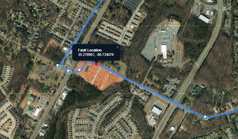
The pin is draggable
If field conditions tell you the actual break is a short distance from the calculated pin, drag it to the correct spot — it will snap to the route line rather than floating off of it. Undo is available if you want to go back to the calculated position.
The circle around the pin is your uncertainty radius
This isn't decoration — it's an honest measure of how confident the tool is, based on the documented slack between the nearest splice points on either side of the fault (see "Why your GIS export matters" above). A tight circle means the route was well-documented near the fault; a wide circle means it wasn't. Treat the circle as the real search area, not the pin as an exact promise.
End Location pin
For FTTx circuits where the fault needs to be understood relative to the customer's premises rather than just the OTDR launch point, an End Location pin can be set at the far end of the circuit. With manual draw, the fault-location estimate progressively narrows as more of the route gets documented — starting as a wide circle, narrowing to a sector, and eventually to a confident point as detail is added, similar to a radar sweep closing in on a target.
Documenting as-built parts
Manual Draw isn't just for fault-locating — it doubles as an as-built capture tool for anything you actually build along the route. As you draw, drop a pin for every splice enclosure, distribution splitter, tap, or other piece of hardware you install, right at its real GPS location.
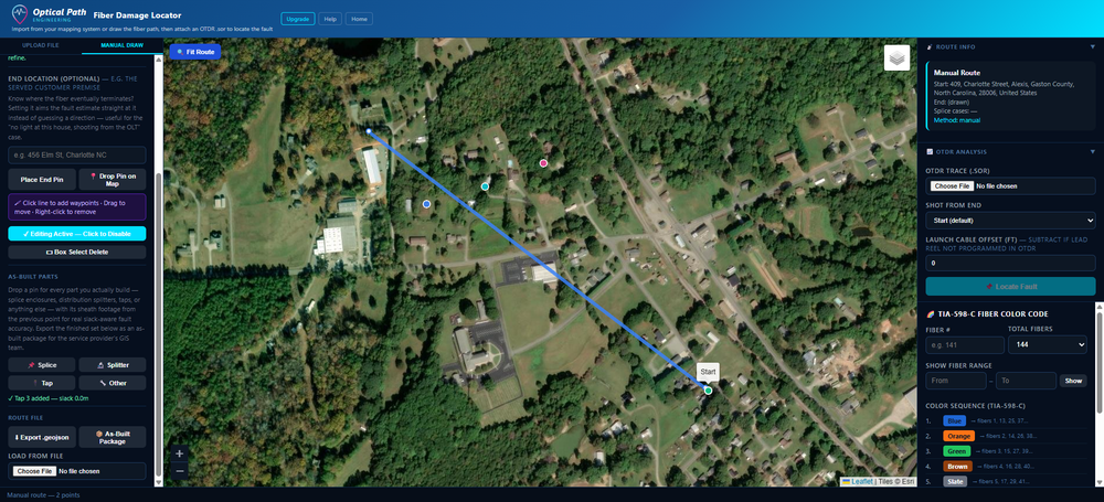
Each part type gets its own color and its own fields — a split ratio for splitters, a tap value and output count for taps, a free-text description for anything else. Enter the sheath footage from the previous point on any part (not just splices) for the same slack-aware fault accuracy a documented vendor import gets.
Branching off a splitter or tap
Real FTTx isn't one straight line — a splitter or tap fans out into several physical legs. Click a placed splitter or tap pin's popup and choose Add Branch From Here to draw a new leg starting at that part, exactly like the main route. A branch can itself contain another splitter with its own branches, for cascaded splits. The Branches panel lists every leg — click one to make it active, so its own parts, OTDR trace, and Locate Fault all apply to that specific leg instead of the trunk. Exporting the As-Built Package from any leg always bundles the whole family.
Attaching OTDR evidence to a splice
Click a placed pin's popup and choose Edit / Attach OTDR to upload the actual .sor trace shot at that splice. The trace is parsed and every event is listed — pick the one that's this splice, and its loss (dB) and distance are saved alongside the raw trace file as auditable proof, not just a number you typed in.
Exporting the as-built package
Once your parts are documented, click As-Built Package in the Route File section to download a single .zip containing a CSV, a branded Excel workbook, a GeoJSON file (route + every part as GPS points, ready to import directly into most GIS systems), and a labeled PDF map — everything a service provider's GIS team needs to record what you actually built, in one file instead of separate paperwork.
Sharing your result
Once you're satisfied with the fault location, use Export PDF map (next to the fault result) to download a one-page map — route, fault pin, and location details — as-built documentation you can hand directly to a repair crew or a contracted company's design team without them needing access to the tool itself. Available on every plan.
For a quicker handoff, Open in Google Maps puts the exact position in front of a repair crew or dispatch with one link — no login required on their end.
If you built the route with manual draw, you can also export it as a .geojson file to reuse next time you need to reference that same path — building your own cable-path library over time instead of redrawing it from scratch on a repeat visit.
Auto-save
Your route and any manual adjustments (dragged waypoints, moved fault pin) are auto-saved before a fault location is calculated, so a browser refresh or an accidental tab close doesn't cost you the work you've already put in. You don't need to click a separate "save" button before locating a fault.
Frequently asked questions
We're here to help
Email support@opticalpathengineering.com and we'll help you work through it — whether that's a specific OTDR model, a GIS export that isn't importing cleanly, or anything else in this guide.