The four-step process
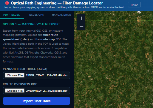
Export from your mapping system
For Option 1, export splice case GPS coordinates and measured cable footage from your internal GIS or network mapping platform as a spreadsheet or CSV — most platforms support one or both formats natively.
- Compatible with Esri ArcGIS, OSPInsight, Cityworks, QGIS, and others
- .xlsx and .csv both supported, same column layout either way
- Splice case GPS coordinates read directly from the file's node columns
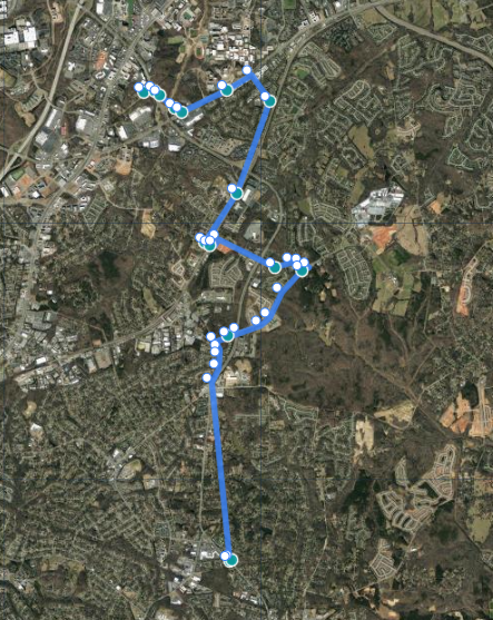
Auto-route with smart road-snapping
Between each pair of splice case coordinates, we check whether a real road plausibly runs along the fiber's path — not just whether one exists nearby. A road route is only trusted when it isn't a significant detour past the direct distance, and when it makes continuous progress rather than looping or backtracking around a block or interchange. Otherwise the segment falls back to a straight line — an honest guess instead of a misleadingly road-realistic wrong one.
After import, drag any waypoint on the map to match the actual cable path — buried conduit, aerial spans through a field, or anywhere the automatic routing didn't get it exactly right.
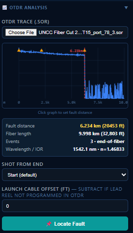
Upload the OTDR .sor trace
Drop in the OTDR file. We parse it with the pyotdr library — extracting the event table, loss profile, and fiber length. The fault distance is identified as the first reflective or loss event past the launch cable.
If the trace was shot from the far end of the circuit (common when re-tracing after an initial test from the other direction), toggle "Shot from End" — the fault distance is measured from the opposite anchor.
For Option 1, the measured cable footage per span (from the spreadsheet/CSV's egress_footage_ft column) is stored as slack_m per vault and used to scale the distance walk. Option 2 (manual draw) gets the same treatment for any span where you documented a splice enclosure's sheath footage as you drew it — undocumented spans fall back to raw geographic distance along the polyline.
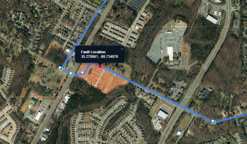
Locate fault — GPS pin on map
We walk the stored route geometry using cumulative Haversine distances, accounting for the cable footage slack in each span. When the accumulated distance equals the OTDR fault distance, we interpolate the exact GPS coordinate.
That coordinate is reverse-geocoded via Nominatim to produce a street address. A red pin drops on the satellite map. The result is ready to copy-paste into CAD, dispatch, or Google Maps.